What Is Ultrasound and Where Is It Used?
If an external force acts on an elastic medium such as a gas, a liquid or a solid, an undulating propagation of pressure and density fluctuation occurs in space and time, starting from the point where the force is applied. This known as sound.
Ultrasound is the term used when the frequency of the propagating wave exceeds 16,000 Hz, making it undetectable for the human ear. The frequency range for ultrasound is up to 16 GHz, i.e., 16 billion cycles per second.
Industry, medical technology and research use ultrasound for many purposes. The best known field of application is sonography, also known as echography. Here, ultrasound is used to generate images of tissue and organs. The great advantage of sonography over other imaging methods in medical technology is that sound waves are harmless and can even be used for unborn babies.
In addition to medical imaging, low sound intensities are also required for applications in measurement technology. The intensity of the sound describes the power that hits a certain surface. If this exceeds 10 W/cm2, it is referred to as high-power sound. In contrast to low-power ultrasound, high-power ultrasound causes material changes or even destruction and is therefore suitable for use in material processing, ultrasonic cleaning or in the medical field in >> Lithotripsy.

How do Piezo Elements Generate Ultrasound?
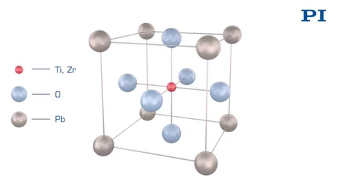
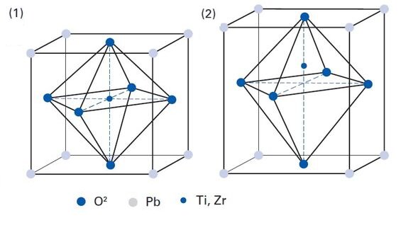
Piezoelectric ceramics are the best basis for generating and detecting ultrasonic waves.
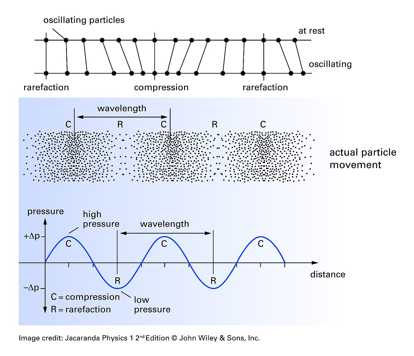
Charge carriers are shifted in piezoelectric materials under the influence of an electric field, which leads to a macroscopic change in length (inverse piezoelectric effect). If the applied voltage is an alternating voltage, the particles in the medium, e.g. in the air, start to vibrate. Pressure fluctuations occur. Rarefaction of the particles leads to lower pressure, and compression to increased pressure. The wavelength of the sound describes the distance between two rarefaction or compression areas. The resulting sound waves propagate in the surrounding medium. The speed of the sound varies according to the density and the elastic properties of the medium.
A basic distinction is made between longitudinal and transverse waves. In the case of longitudinal waves, oscillation occurs in the plane of their propagation. They can propagate in liquids and gases, but also in solids. Transverse waves, on the other hand, oscillate perpendicular to their direction of propagation and this is only possible in solids. Both wave modes can be converted to the other mode by reflection or refraction at boundary areas to denser materials.
Electroacoustic Transducers
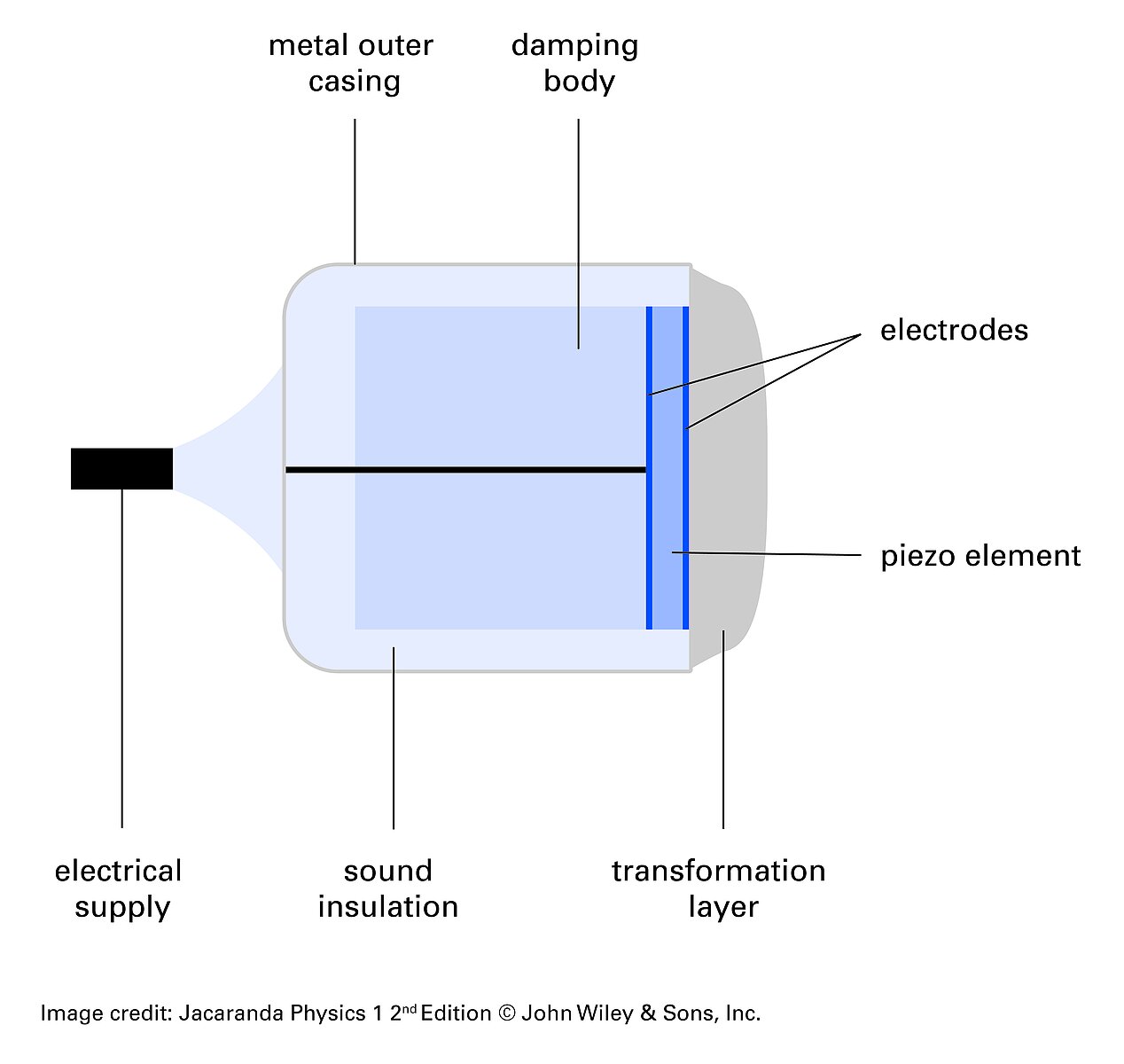
Electroacoustic transducers, also known as transducer, convert acoustic energy to electrical energy or vice versa. The consist of an active piezo element, a housing, and electrical connectors.
An important parameter for transmitting sound waves is the characteristic acoustic impedance, also known as wave resistance. It depends on the density of the medium and the speed of sound. The difference between the sound impedances of two media determines whether and how well the sound waves can be transferred from one medium to another. If this difference is too large, the sound is reflected and transmission is not possible.
An adaptation layer (transformation layer) between the piezo element and the surrounding medium In the transducer ensures the smallest possible difference in sound impedance and therefore increases the transmission quality. Ideally, the thickness of this layer is equal to a quarter of the sound's wavelength (λ/4).
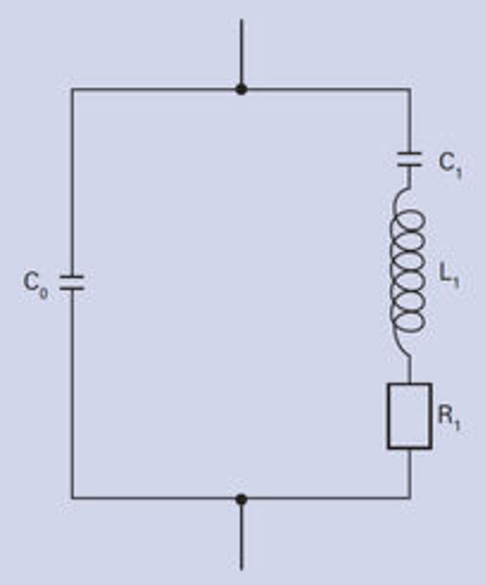
The electromechanical behavior of a piezoelectric element stimulated to oscillation can be represented by an electrical equivalent circuit diagram.
C0 is the capacitance of the dielectric. Serial connection of C1, L1, and R1 describes the change in mechanical properties such as elastic deformation, effective mass respectively inertia, and mechanical losses as a result of internal friction. However, this description of the resonant circuit only applies to frequencies in the vicinity of the mechanics' intrinsic resonance.
Most piezoelectric material parameters are determined by means of impedance measurements on special test bodies at resonance.
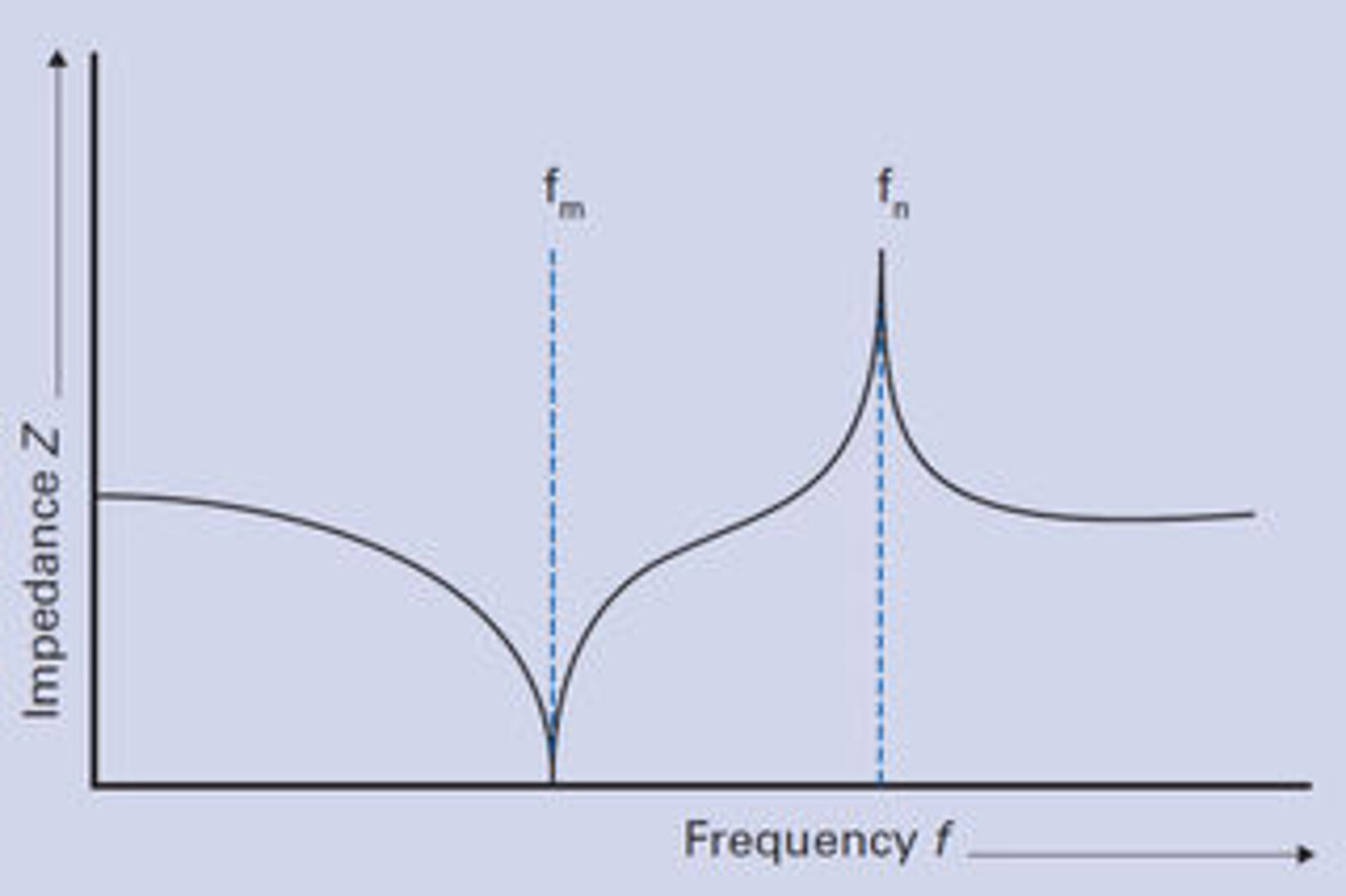
The Z impedance, also known as apparent resistance, is a complex alternating current resistance, where the real part stands for the ohmic resistance and the imaginary part for the reactance. The impedance is described by the length of the complex vector and a phase angle ϕ.
Mechanical resonances can be measured electrically by >> Coupling Mechanical and Electrical Oscillation. The serial and parallel resonances are used to determine the piezoelectric characteristic values. These correspond in good approximation to the impedance minimum fm and maximum fn. The impedance is measured as standard during quality inspection of piezo components and assemblies. Conclusions can be drawn based on the shape and dynamics of the impedance curve, for example, defects in the piezo component or the quality of adhesive layers.
Ultrasonic Measuring Principles with Piezo Elements
Piezo ultrasonic sensors offer high precision and reliability over large measuring ranges as well as long-term stability and are compact. They do not require optical transparency. Basically, a distinction is made between two measuring principles:
1. Runtime Measuring
1. Runtime Measuring
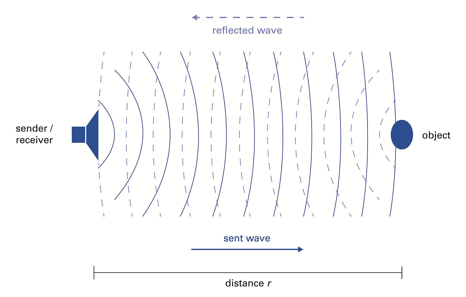
The piezoceramic element serves as transmitter and receiver during runtime measuring whether measuring the gap, detecting objects or for >> Measuring Flow.
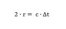
The piezoceramic element emits an ultrasonic pulse. The sound waves triggered by this propagate and and then hit an object. They are then reflected and partially absorbed. The same piezo element receives the reflected waves. The transmit time difference Δt between emitting and receiving the sound waves provides information on the distance r between the sound source and the object. Once the speed of the sound c in the surrounding medium is known, it is possible to calculate the gap r:
2. Doppler Effect
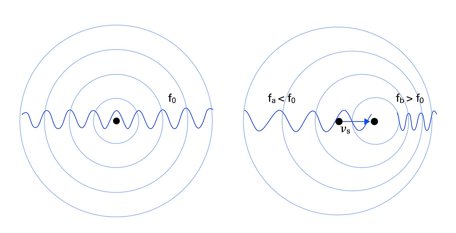
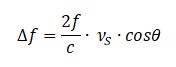
The principle of the Doppler effect is used to measure the flow rates or flow velocities of contaminated media, e.g., suspended particles or air bubbles. After emitting an ultrasonic pulse, the ultrasonic waves (f0) are scattered or reflected by liquid particles. The resulting shift of frequency Δf between the reflected wavefront that was emitted and received by the same piezo transducer is proportional to the flow velocity vS of the particles. The angle θ between the direction of the emitted ultrasonic pulse and the measuring path must be taken into account:
The direction of flow can also be determined by the frequency change. When the liquid particles approach the sensor, the wavelength of the sound shortens and the frequency increases (fb) because the sound waves are pushed in front of the particles and compresses them. Conversely, the wavelength increases and the frequency of the sound decreases as the particles move away from the sensor (fa). This frequency change Δf of the sound waves can be detected and compared with the sound frequency of the emitted ultrasonic pulse.
Applications for this include building services engineering for determining the consumption of water or heating energy as well as in the medical field for recording blood flow velocity and direction.